
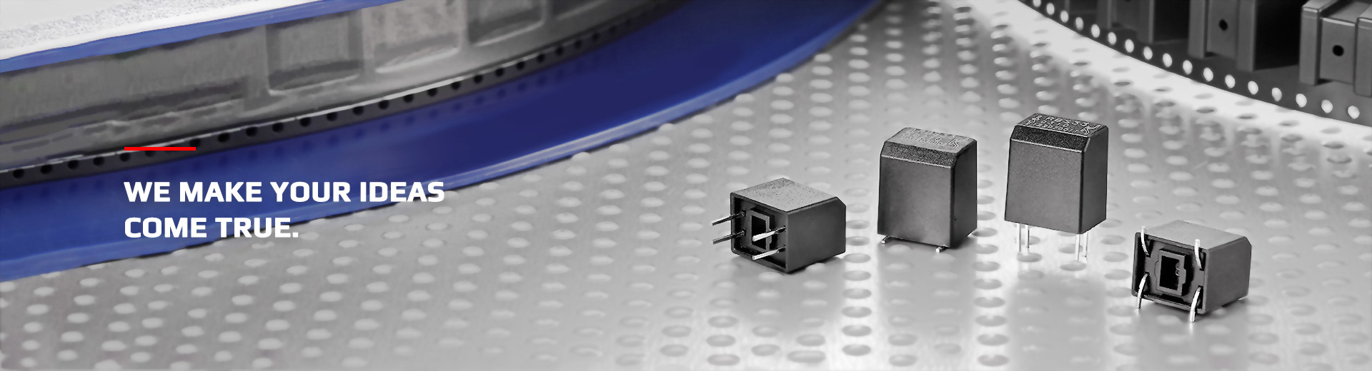
How to Choose an Optical Ball Switch? 7 Key Evaluation Factors Engineers Should Not Overlook
How to Choose an Optical Ball Switch?
Learn the seven key factors for selecting an Optical Ball Switch, including trigger angle, installation direction, output signal, power requirements, PCB layout, environmental interference, and verification methods. This guide helps engineers quickly identify the most suitable tilt detection solution for their application.
Why Is Selecting the Right Optical Ball Switch Important?
An Optical Ball Switch combines a ball mechanism with optical detection technology to provide a stable and reliable ON/OFF signal when a device tilts, tips over, or changes orientation.
Compared with conventional mechanical ball switches, optical designs offer several advantages, including contactless detection, no mechanical contact wear, longer service life, and more stable signal output. They are therefore widely used in:
However, selecting an Optical Ball Switch involves more than simply considering its size or package type. Product structure, power supply conditions, and the actual operating environment must also be carefully evaluated to achieve optimal performance.
7 Key Evaluation Factors for Selecting an Optical Ball Switch
How Should the Seven Selection Factors Be Evaluated?
Determine the Required Trigger Angle
The first step is to determine the angle at which the product should begin generating an output signal. Different applications require different trigger angles.
| Application | Recommended Angle |
|---|---|
| Tip-over protection for electric heaters | 30°– 45° |
| Safety protection for electric fans | 30°– 45° |
| Anti-tip protection for industrial equipment | 45°– 65° |
| Orientation detection | Depending on product requirements |
Selecting an unsuitable trigger angle may result in:
- Premature triggering
- Failure to comply with safety requirements
- Users incorrectly assuming that the product is malfunctioning
Confirm the Installation Direction
An Optical Ball Switch still relies on gravity to move the internal ball and control the optical path. Therefore, the installation direction is extremely important.
During the engineering design stage, confirm the following:
- Is the PCB installed horizontally or vertically?
- Is the user's operating direction fixed?
- Could the product be placed upside down, sideways, or completely inverted?
Even when the same model is used, different installation angles may produce different trigger results.
Confirm the Output Signal Type
The output configuration may vary slightly between different Optical Ball Switch models. The system's signal-reading method should therefore be confirmed in advance.
Common evaluation items include:
- Whether the output is a digital ON/OFF signal
- Whether an MCU is required to interpret the signal
- Whether a pull-up or pull-down resistor is required
- Whether software filtering or debounce processing is required
For products used in high-vibration environments, software-based signal validation is also recommended to prevent temporary vibration from causing false triggering.
Evaluate the Power Requirements
An Optical Ball Switch typically contains:
- An LED light-emitting component
- A photodetector, such as a phototransistor
The following electrical conditions should therefore be confirmed:
- Operating voltage
- Operating current
- Standby power consumption
- Whether the MCU can drive or interface with the device directly
Power consumption is especially important for battery-powered products, portable devices, and IoT sensors.
Consider the PCB Layout
A well-designed PCB layout can significantly improve sensing stability. The following points should be considered during the design stage:
- Prevent mechanical structures from blocking the optical path
- Avoid reflective materials that may interfere with optical detection
- Reserve sufficient soldering space
- Include test points
- Avoid placing the switch too close to high-temperature components
A good PCB layout can also reduce subsequent assembly and maintenance costs.
Evaluate the Operating Environment
Operating conditions vary significantly between products. The following environmental factors should therefore be evaluated:
- High temperature
- Low temperature
- Dust
- High humidity
- Strong vibration
- Interference from external light sources
For products installed in industrial equipment, outdoor equipment, or automotive systems, verification under actual operating conditions is highly recommended rather than relying solely on laboratory test results.
Establish a Complete Verification and Testing Process
After the design is completed, a comprehensive verification process should still be established. The test plan should include at least:
Through comprehensive verification, engineers can confirm that the product maintains consistent and reliable sensing performance under different operating conditions.
Selection Should Not Be Based on a Single Specification
The actual performance of an Optical Ball Switch is influenced by trigger angle, installation orientation, product structure, power conditions, vibration, environmental factors, and the system's signal-processing method.
Evaluating these conditions together during the early design stage can reduce the risk of later PCB revisions, mechanical rework, and software adjustment.
Choose the Optical Ball Switch Based on the Complete Application
An Optical Ball Switch can provide stable and reliable tilt and tip-over detection, but the most suitable model should always be selected according to the actual application conditions.
Engineers should evaluate trigger angle, installation direction, output signal, power requirements, PCB layout, operating environment, and verification testing, then confirm the final design through application-level testing.
Need Help Selecting the Right Optical Ball Switch?
Contact the OncQue team to discuss your product structure, trigger angle, installation method, electrical conditions, testing requirements, and application needs.
- Trigger angle and installation review
- Optical Ball Switch model selection
- Output signal and circuit discussion
- Application and reliability evaluation