
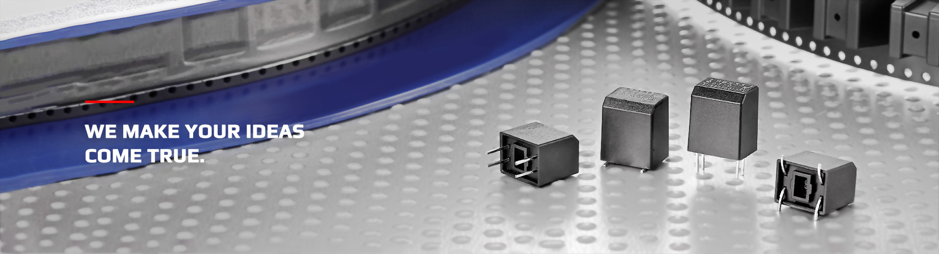
PCB Design Directly Affects Trigger Performance
The actual trigger performance of an Optical Ball Switch is closely related to PCB design and mechanical integration. Even when the component specifications meet the design requirements, improper installation orientation, signal routing, or surrounding mechanical structures may affect stability after mass production.
Three Key PCB Design Considerations
Confirm Installation Orientation and Product Posture
Because the internal ball is affected by gravity, the PCB installation angle, component orientation, and product housing posture should all be clearly defined in the design drawings.
- Confirm the final PCB installation orientation
- Define the component mounting and rotation direction
- Confirm the product's normal operating posture
- Prevent orientation differences between prototypes and production units
Confirm Power and Signal Routing
Optical sensing structures typically use an LED emitter and a photodetector. The design should therefore confirm the operating voltage, operating current, signal output method, and signal interpretation requirements.
- Confirm the operating voltage
- Confirm the operating current
- Confirm pull-up or pull-down resistor requirements
- Evaluate whether basic filtering is required
Use Firmware-Based Signal Validation
For products used in vibrating or moving environments, firmware-based signal validation is recommended to reduce false triggering caused by brief changes in orientation.
- Signal debounce
- Time-delay validation
- Multiple-sample confirmation
- Reduce false triggering caused by temporary posture changes
Items to Confirm Before PCB Layout
Recommended Design Verification Process
Conclusion
The actual performance of an Optical Ball Switch depends not only on the component specification, but also on PCB orientation, product posture, power and signal configuration, and firmware logic.
Defining these conditions clearly during the early design stage can reduce differences between prototype testing and mass-production assembly while improving overall product stability.
Let OncQue Help Evaluate Your PCB Layout and Optical Ball Switch Configuration
If you are evaluating PCB layout, installation orientation, or signal configuration for an Optical Ball Switch, contact the OncQue team to discuss your application requirements.
- PCB installation orientation review
- Component orientation and product posture verification
- Power and signal configuration discussion
- Vibration environment and firmware logic recommendations